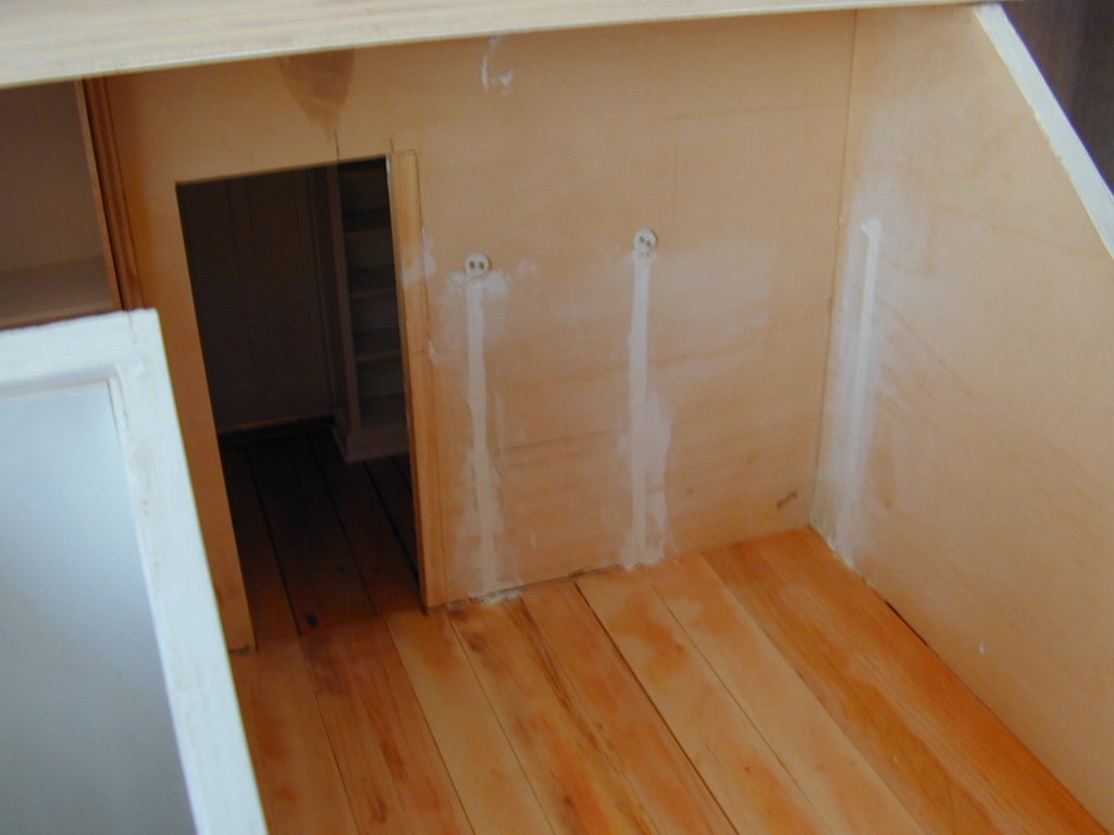
| When the
miniature house was completed and all the lighting in place, it was
discovered that two of the first floor circuits were shorting out.
The dollhouse had to be completely disassembled, the spackle removed
and the wires checked for continuity. It was found that the short
was in the miniature electrical outlets and not in the wiring. The
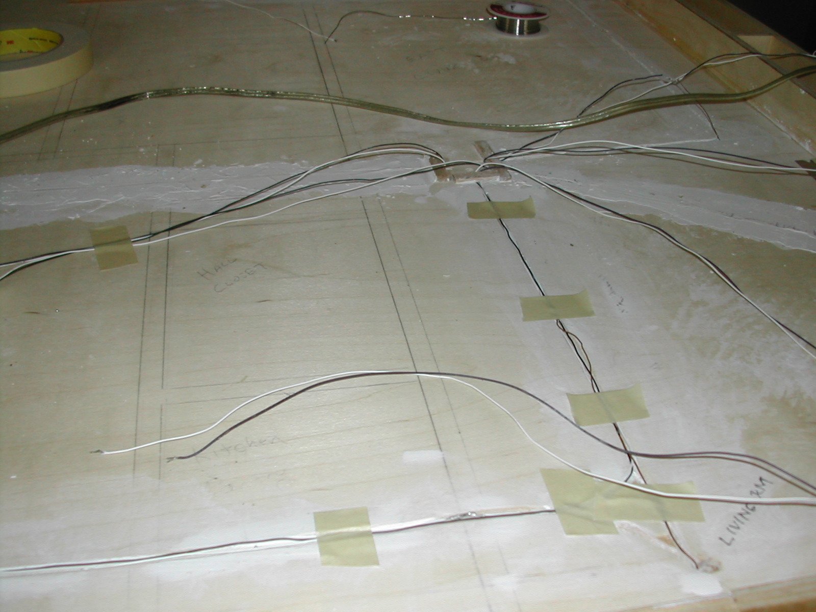
outlets were then replaced. Shown in the photograph is
the underside of the first floor where the spackle was removed and the
wires uncovered. The wires were then given a continuity check with a
voltmeter. If you look carefully at the enlarged photograph, you can
see, in the far corners, the 1" diameter centering posts that fit into
the base to
properly position the first floor. |
 |
| The second photograph shows a different view. The wires are temporally held in place with masking tape while the continuity check is made. One may also note that all the wires lead to the main chimney chase which is behind the kitchen fireplace. |
 |
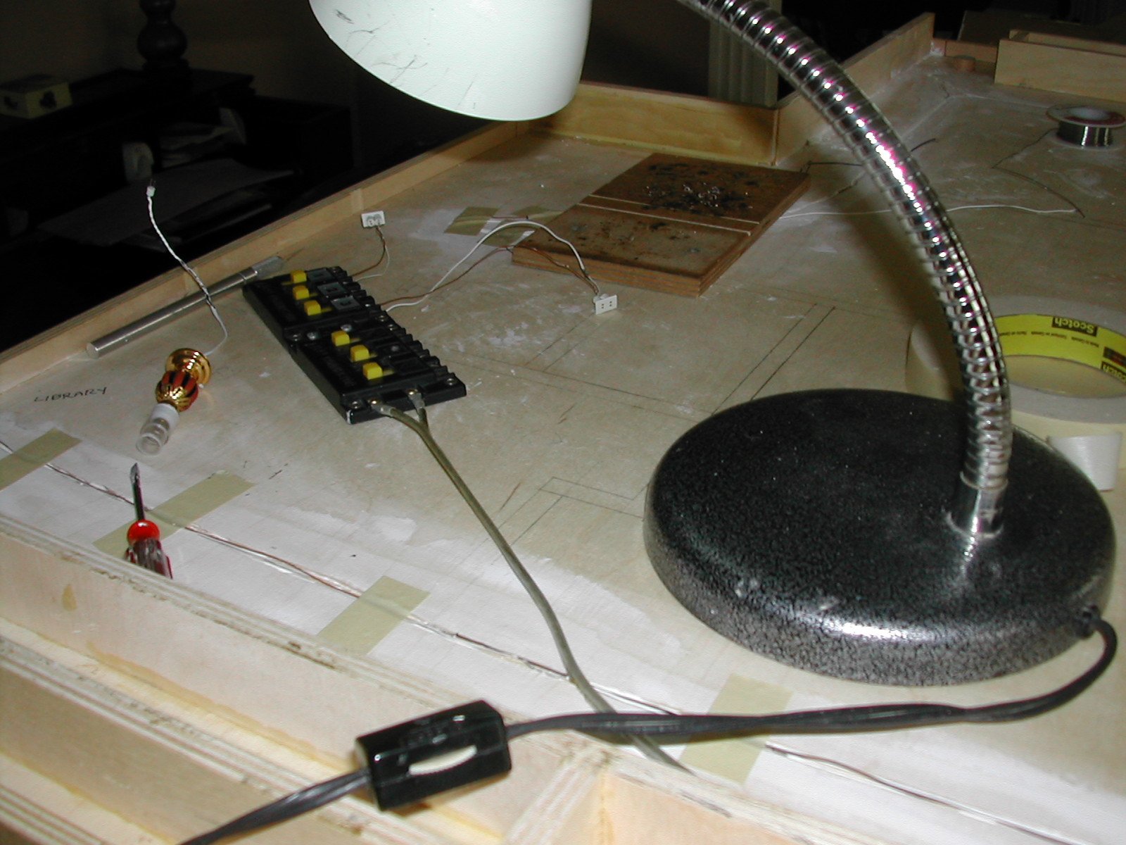
| The next
photograph shows the final continuity check which consisted of plugging
a light into the electrical outlet to see if it worked. One of the
model
railroad switches is also part of the circuit check. |
 |
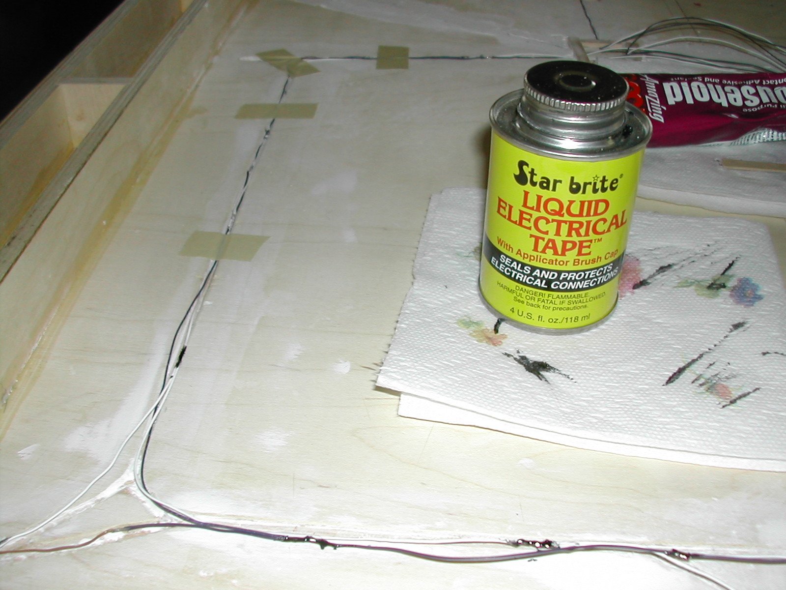
| After the
continuity check is satisfactorily made to the exposed connections, the
wire was coated with liquid electrical tape to protect the connections
from corrosion. The wires were then placed into the routed grooves and
spackle was reapplied. |
 |
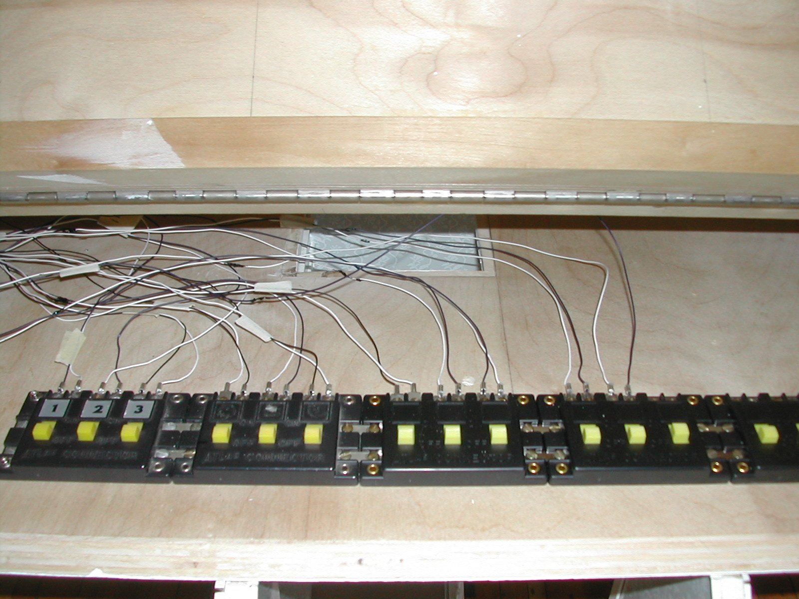
| The
photograph on the right shows the wires being attached to the model
railroad switches in the attic. Each wire is color coded (black and
white) and each circuit is numbered with an attached tag so that it
could later be properly identified. |
 |
| The
photograph on the right shows the wiring to the sconces in the bathroom
and on the wall to the right, the sconce in the computer room. Spackle
has been applied to cover
the wires and sanded flush with the wall and readied for a prime coat
of
paint before the wainscoting was installed and the wall paper applied. |
 |
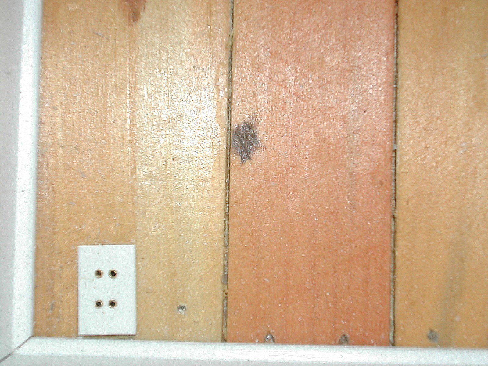
| The
photograph on the right shows a close up view of the electrical outlet
mounted in the floor of the upstairs guest bedroom. All outlets are
positioned
exactly where the real outlet are located. |
 |
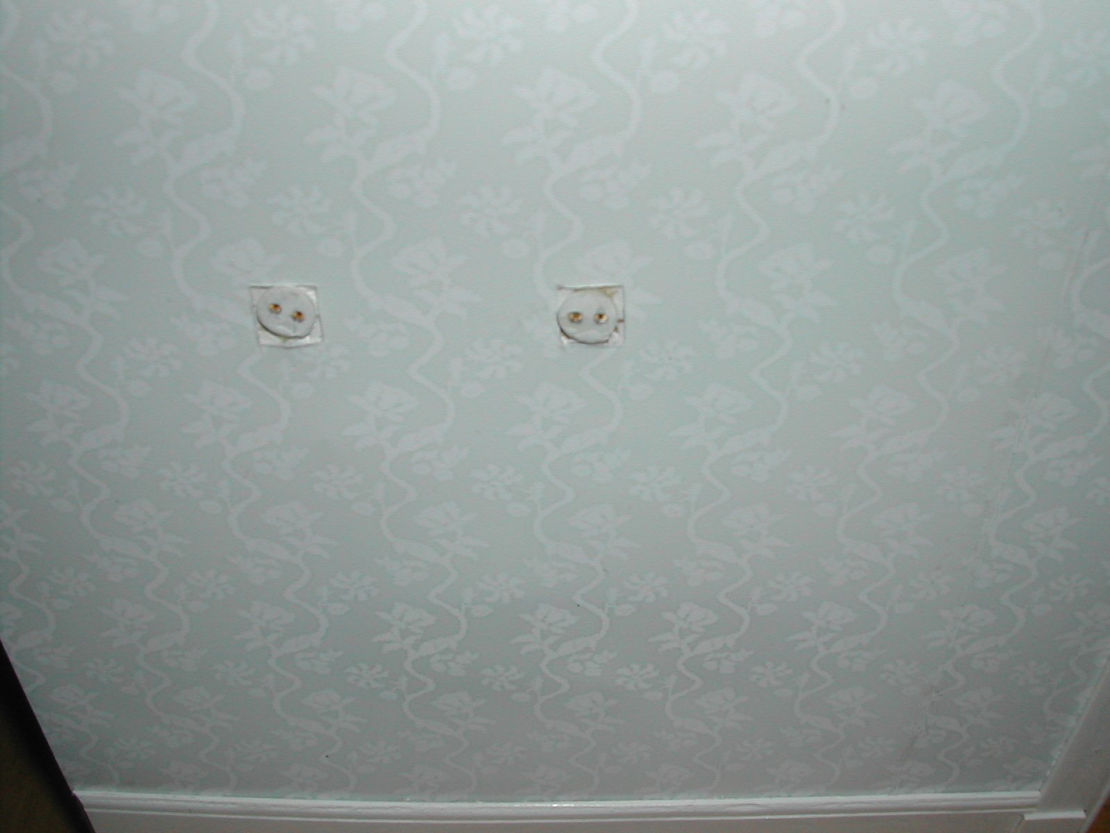
| This
photograph shows where the wall sconces will be mounted in the front
hall as you
enter the house opposite the front door. The wallpaper is shown already
in place and ready for the
sconces to be plugged in. |
 |